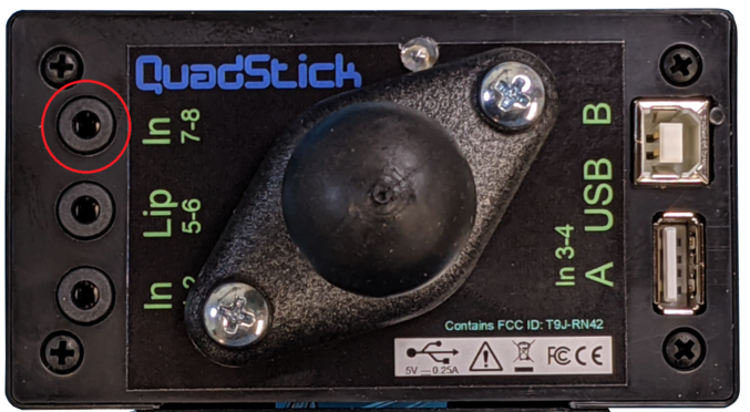
The upper input jack on the back of the Quadstick or a Singleton is a 3.5 mm stereo connector with the two input circuits (Tip & Ring) and Shield (or Ground). When ordering, two choices for this jack are available: Input or Output. If this jack is labeled Out on your Quadstick, these inputs are not available. See below for Output.
Input:
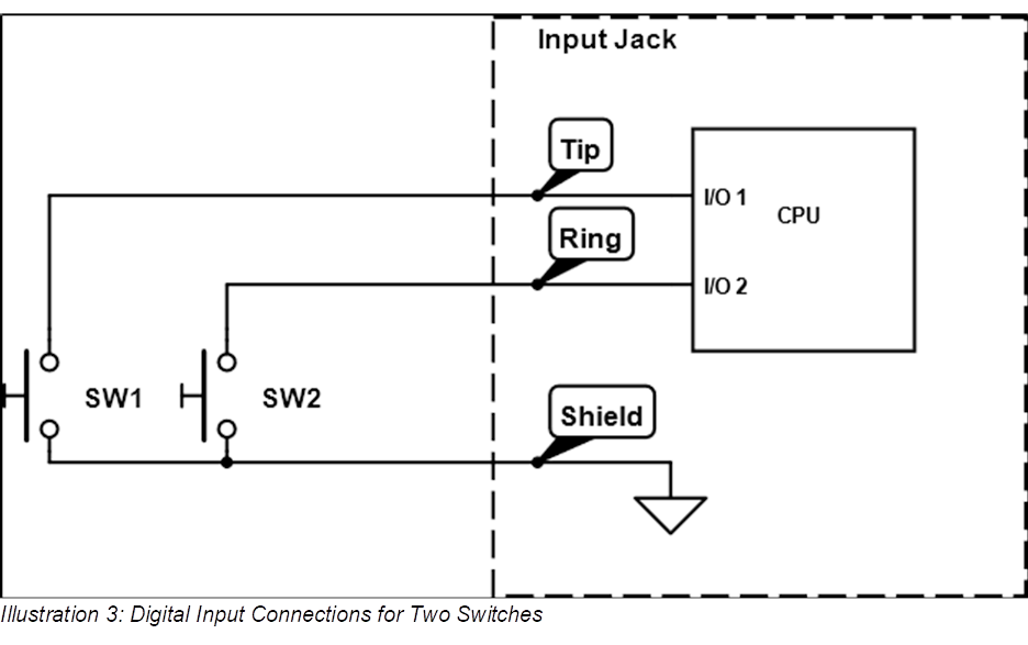
Two switches may be connected using the following circuit.
Input Name
Description
Delay
digital_in_7
Input Jack - Ring to Shield (SW2)
instant
digital_in_8
Input Jack - Tip to Shield (SW1)
instant
Table 2: External Digital Inputs 7 & 8
When using two Switches in this manner, the Quadstick can detect the switch closures independently and simultaneously.
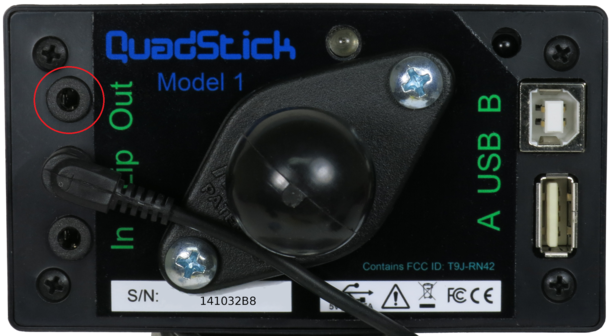
Output
:
This jack has two optically isolated relays that can be used to control devices that work with ability switches.
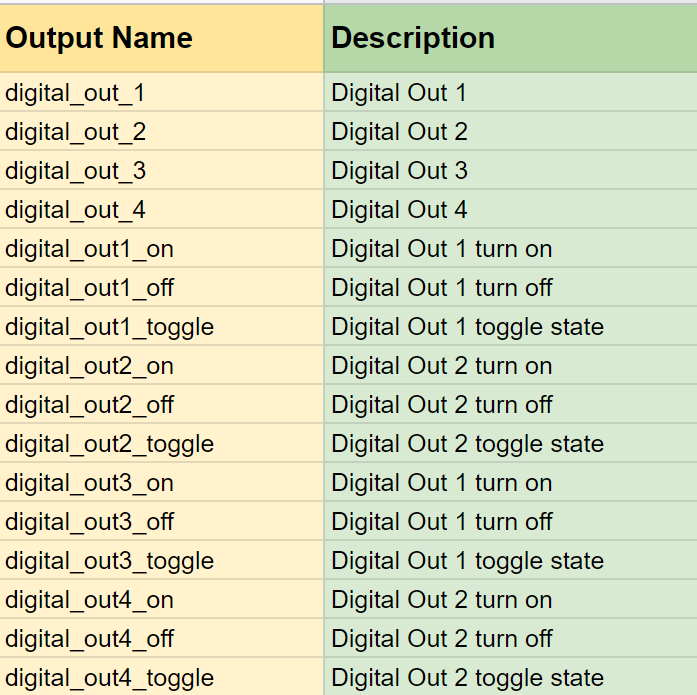
The digital outputs can be controlled directly, just like a controller button, or used with separate inputs that control the on, off, or toggle status of the output. Only digtal outputs 1 and 2, which have 24 VAC/DC solid state relays, are available on the top jack. Digital outputs 3 and 4 are 3.3 volt logic level ouputs available on the bottom IN jack.
The outputs names "digital_out_1" through "digital_out_4" can also be used in a Preferences sheet to force the output to an inital state when the configuration file is loaded. This can be used to help the user confirm they have loaded a specific configuration file.
The status of the digital outputs are displayed on the four green LEDs along the right hand side of the enclosure. The green LEDs are associated with the digital outputs from top to bottom with digital outputs 1 through 4. The green LEDs are often used to indicate some internal status.
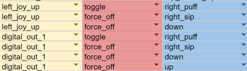
In this example, forward motion (left_joy_up) is controlled by a puff on the side tube. The digital_out_1 output is controlled in parallel with the left_joy_up so that the user has a visual indication of the left_joy_up status.