The joystick measures the deflection from the home, or center position and produces both continuous analog values and discrete position signals, depending upon the output to which it is connected. When used for the Mouse or one of the Game Pad joysticks, the position is reported as continuously variable with the movement of the joystick. The sensitivity of the joystick movement is controlled by two overall preference settings for the minimum and maximum range of motion as well as four multipliers to individually adjust the movement in the four directions: up, down, left & right. The general topic of Preference settings is covered in a later chapter.
These settings can be adjusted using the Quadstick Manager Program's Joystick tab.
|
joystick_deflection_minimum
|
9
|
percent
|
Defines center dead zone. Percent of physical movement
|
|
joystick_deflection_maximum
|
30
|
percent
|
Defines physical deflection scaled to 100% Signal
|
|
deflection_multiplier_up
|
140
|
percent
|
Adjusts joystick deflection value in the UP direction
|
|
deflection_multiplier_down
|
130
|
percent
|
Adjusts joystick deflection value in the DOWN direction
|
|
deflection_multiplier_left
|
100
|
percent
|
Adjusts joystick deflection value in the LEFT direction
|
|
deflection_multiplier_right
|
100
|
percent
|
Adjusts joystick deflection value in the RIGHT direction
|
|
joystick_dead_zone_shape
|
1
|
|
0=Square, 1=Circle
|
|
anti_dead_zone
|
0
|
percent
|
Counteracts the dead zone built into the Game Console's joystick software
|
|
joystick_warning
|
400
|
percent
|
Joystick position beyond full scale that will flash the leds
|
|
joystick_alarm
|
500
|
percent
|
Joysitck position beyond full scale that will buzz the speaker
|
Dead-Zone
The joystick_dead_zone_shape, and the effect it has is illustrated in the next two images.
When the dead zone is a square, it tends to favor horizontal or vertical movement when the joystick position is nearly aligned with one of the two axis. This makes it more difficult to move at small angles near one of the axes. The movement tends to snap to the axis.
When the dead zone is a circle, the amount of movement in each axis is in proportion to the angle the joystick relative to the axes, the movement does not snap to one of the axis and has a more natural feel. The default value for this setting is for circle (1). If you prefer the action of the original square dead zone instead, the preference can be set to 0 in the misc tab in the QuadStick Manager Program by turning off the Enable Circular Dead Zone check box.
Certain applications where the outputs controlled by the two joystick axis are not related, may work better with the square dead zone. This can be controlled on individual mode sheets or on a Preference sheet in a game configuration spreadsheet.
joystick_deflection_minimum and maximum
The joystick_deflection_minimum and maximum settings are relative to the full mechanical movement of the joystick. They control the overall sensitivity of the joystick movement. The deflection_multiplier_* values adjust the overall sensitivity for the four individual directions.
In the QMP Joystick tab, the joystick_deflection_* and multiplier values are displayed in the lower right corner.
The joystick_D_Pad_inner and _outer settings are relative to the scaled signal calculated as a result of the earlier deflection settings.
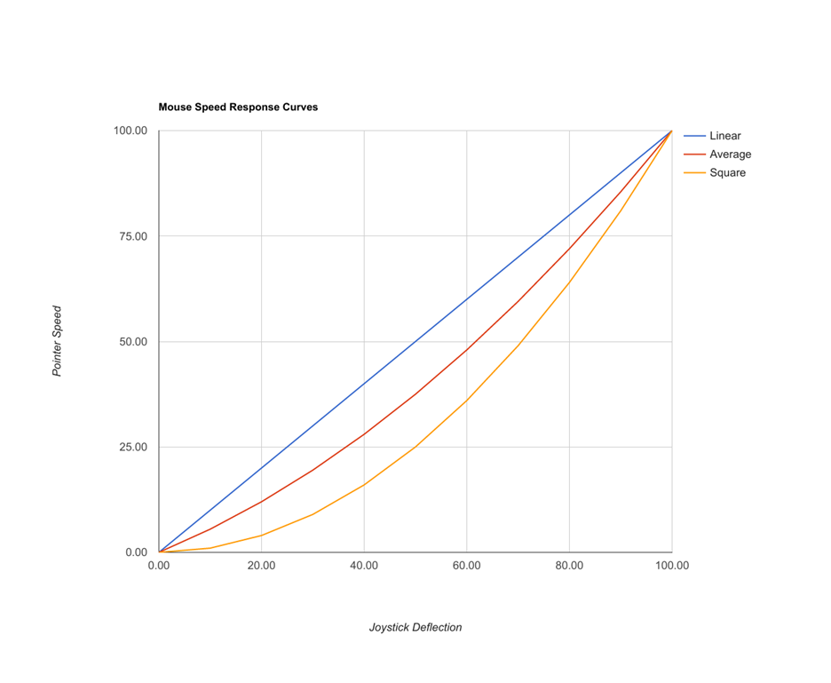
Mouse_speed controls how fast the mouse moves based on the scaled position from the joystick calculations. When adjusting the joystick deflections and mouse speed, first adjust the joystick in a game controller mode, then adjust the mouse speed second.
The mouse_response_curve setting can make the mouse less sensitive near the center position and move much faster when the joystick is moved farther away from the center.
D-Pad Zones
When used with a discrete output, like the D-Pad buttons, the joystick’s position is divided up into a series of zones, such as North, South, East and West, which triggers a signal when the joystick is moved into a zone.
The discrete zones are further divided into the Ordinal directions, North-East, South-East, etc as well as into Inner ring and Outer ring zones, in a manner similar to the dual pressure thresholds for the Sip/Puff sensors. When moving through the inner ring, a tone is produced to indicate the joystick is within the inner ring region and a click is produced when either the time delay expires, or the joystick moves into the outer ring and an outer ring signal is triggered.
The Joystick Discrete Zones diagram shows the active areas to which the joystick can be positioned to trigger a signal. The areas of deeper color saturation, around the Cardinal and Ordinal directions, show where the joystick must be to be detected. The lighter mixed color areas between the eight directions show hysteresis areas where the previous signal will remain active until the joystick enters the next detection zone. For instance, starting at North, the joystick can be moved from the Green area, into the Blue-Green-Gray area towards either NE or NW and still maintain the North signal. It can move back into the Green area and no interruption of the North signal will have occurred. However, once the joystick crosses into the Blue area around NE or NW, that new signal becomes active and will remain active as long as the joystick remains in the Blue area or the adjacent Blue-Green or Magenta areas.
The inner and outer rings operate like the Soft and Hard Sip/Puff pressures: After entering the Inner ring, the user must hold the joystick in the area between the Hysteresis ring and the Outer ring until a timer expires and triggers the signal. A tone that varies with the position will sound until the timer expires. Once the Inner ring timer has expired and the inner ring signal is activated, the joystick has to return to the center position before moving to trigger an Outer ring signal. Once triggered, either the inner or outer ring signals will stay active as long as the joystick stays outside the Hysteresis ring. The joystick deflection between the Outer ring and the maximum deflection is scaled into the pressure applied to the corresponding PS3 button, if so mapped.
The following table contains the name of all the Joystick Zones input signals, with a brief description and if the adjustable delay timer is used to detect the input.
|
Input Name
|
Description
|
Delay
|
|
left
|
Joystick Left Analog value
|
instant
|
|
right
|
Joystick Right Analog value
|
instant
|
|
up
|
Joystick Up Analog value
|
instant
|
|
down
|
Joystick Down Analog value
|
instant
|
|
N
|
Joystick Outer ring North zone
|
instant
|
|
NE
|
Joystick Outer ring North East zone
|
instant
|
|
E
|
Joystick Outer ring East zone
|
instant
|
|
SE
|
Joystick Outer ring South East zone
|
instant
|
|
S
|
Joystick Outer ring South zone
|
instant
|
|
SW
|
Joystick Outer ring South West zone
|
instant
|
|
W
|
Joystick Outer ring West zone
|
instant
|
|
NW
|
Joystick Outer ring North West zone
|
instant
|
|
N_inner
|
Joystick Inner ring North zone
|
delay
|
|
NE_inner
|
Joystick Inner ring North East zone
|
delay
|
|
E_inner
|
Joystick Inner ring East zone
|
delay
|
|
SE_inner
|
Joystick Inner ring South East zone
|
delay
|
|
S_inner
|
Joystick Inner ring South zone
|
delay
|
|
SW_inner
|
Joystick Inner ring South West zone
|
delay
|
|
W_inner
|
Joystick Inner ring West zone
|
delay
|
|
NW_inner
|
Joystick Inner ring North West zone
|
delay
|
Table 1: Joystick Inputs
Sixteen discrete signals can be produced from the joystick using the eight compass directions and the inner/outer rings, plus using the Bite sensor like a Shift key, brings the total to thirty-two.
The deflection ring thresholds and overall sensitivity of the joystick are adjustable by the user. If the inner ring zones are not used in a specific profile, the audio tones are suppressed.